
Fabrication, Specification and Functionalilty of Explosion Proof Control Panels
 By careful design of the electrical installation according to IEC Standards, it is frequently possible to locate a control panels in small hazardous or non-hazardous areas.
When the control panel is to be installed in areas where dangerous concentrations and quantities of combustible gases or vapours are present in the environment, enough protective measures are to be taken to reduce the probability of explosions due to ignition by hot surfaces either during fault or even during normal conditions.
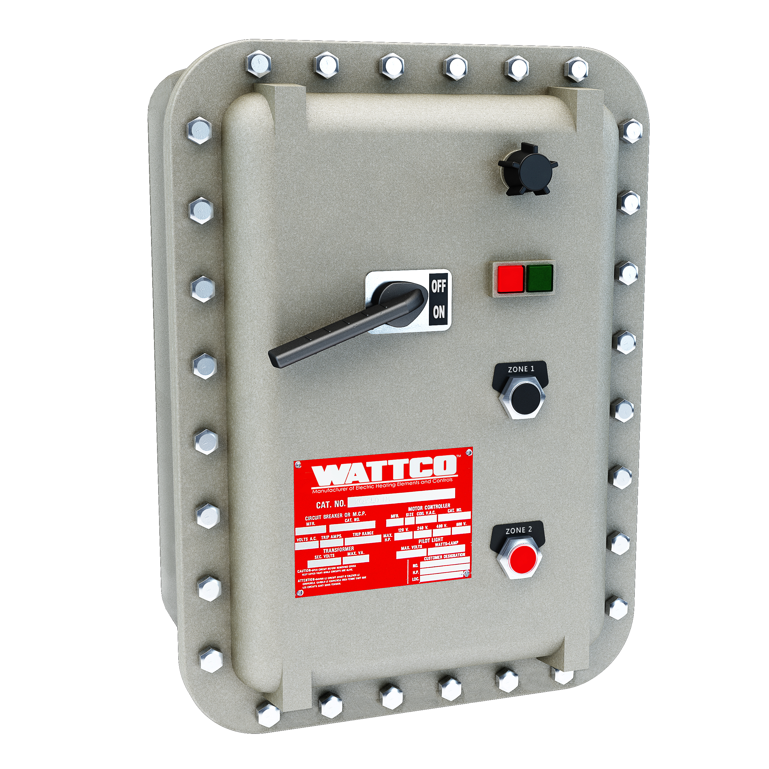
Controls Panels that are responsible for managing, or come into close contact with, explosive elements are enclosed in a specialized container made to withstand high pressure or explosions. These specialized enclosures are also built to contain the explosion so that it does not spread to the surrounding area, potentially harming other machinery or personnel.The term “EXPLOSION-PROOF” describes the joint’s ability to contain an explosion.
Explosion-proof devices have two fundamental characteristics:
a) The enclosure shall be strong enough to resist an internal explosion without suffering breakage or permanent deformation (this is tested with a static overpressure 1.5 times the reference pressure measured during type tests, applied for duration of between 10 seconds and 60 seconds).
b) The passages between the inside and the outside of the enclosure (called lamination joints or flame-proof joints) shall be able to prevent the ignition of the surrounding atmosphere.
* Please note that there should not be additional holes in the enclosures body and cover.
The joints are the contact surfaces between two corresponding parts of the same enclosure (e.g. cover and body) or of several enclosures (e.g. box entry and cable gland) designed and constructed to be able to prevent the transmission of an explosion from the inside of the enclosure to the outside.
Joints may be threaded or not threaded. Non threaded joints can have different shapes: flat, angled, cylindrical, conical, and labyrinth.
The joints shall not permit the release of the hot gases created by an explosion, because the energy and the overpressure generated by the explosion are absorbed by the mechanical structure of the enclosure in the form of heat and the elastic deformation of the enclosure, with a slight, temporary increase in temperature.
Heated elements (gases, incandescent particles, flames, etc.) may pass through the joints. However the joints shall therefore have a sufficiently long and narrow “interstice”. This will allow the super-heated elements to cool as they pass through the interstice towards the outside, where they will no longer be hot enough to ignite an external atmosphere.
It is recommended that the surfaces that come into contact inside the joint (e.g. threads or contact surfaces) be protected against corrosion, but they should not hinder the sealing properties: for example, silicon based grease may be used, but surfaces shall not be painted, nor may any type of tape, such as Teflon, be inserted into the joints, or any other material, such as hemp.
Explosion-proof control panels are generally metallic to ensure the pressure seal and enough length to cool the gases passing through the joint.
To avoid high pressures inside the enclosures during the explosion, the dimensions of the equipment shall be limited. They can also be provided internal partitions.
However, non-metallic enclosures are permitted with a free internal volume up to 3000 cm³, provided that they pass specific tests relating to their surface electrical resistance. The use of plastic materials in explosion-proof equipment is limited to transparent parts and small apparatus, devices, and/or components (e.g. switches, button contacts, LED lights, etc.).
Gasket seal may be used to improve the level of protection of the enclosure (IP level), but it should have no influence either in terms of preventing the entry of the explosive atmosphere into the construction or of flame-proofing.
Installation of Equipment
Where the equipment is to be installed in areas of high mechanical risk, additional measures such as the provision of guards for light transmitting parts may be necessary. However, such additional measures should not impair the integrity of the type of protection. Where possible, a higher IP code shall be recommended for safeguarding of the equipment provided it does not cause a higher impact on the cost. The manufacturer shall provide clear installation instruction.
Automatic Electrical Protection
All circuits and equipment in hazardous areas should be provided with means to ensure automatic disconnections in the event of overcurrent, overload, single phasing or earth fault conditions.