
Immersion Heaters and Mechanisms of Heat Transfer
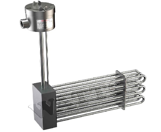
Immersion heaters are a popular application in the oil & gas, petrochemical and manufacturing industries. Their operational principle is simple and is based on the direct heating of a fluid body when the immersed heating element is operating while placed inside the fluid body.
The most common design involves a heating element directly submerged in the target medium. The elements transfer heat to a colder mass via conduction. However, depending on the presence of a flow of the fluid or even the occurrence of a flow due to temperature changes, the heat transfer can also occur via convection. 
In most applications, the immersed heater is an electrically powered resistance that reaches efficiencies of 100% in the energy transformation. Since the actual heating resistance is covered, the monitoring of the energy transformation efficiency always presents a short hysteresis which is not to be confused with a loss of efficiency.
The electrical energy passing through the resistance is completely transformed into thermal energy which first is used to increase the temperature of the cover and the rest of the mechanical components of the heater, before it can be used to raise the temperature of the actual fluid. Modern controllers include this time delay in the calculations for the ON/ OFF or electrical power decrease/ increase signals to the power source.
Mechanisms of Heat Transfer
Generally, heat transfers via three mechanisms; conduction, convection and radiation.
Conductions
The first is observed when two solid phases [or non-moving fluids] are in direct contact with each other. The transfer rate, in this case, is proportional to the current [dynamic, in opposition to a steady state] difference of temperatures of the two bodies, the area of contact and a conductivity efficient for heat transfer, ‘k’. Thus, if one requires to optimize/ modify/ monitor the heat transfer there are three factors to address.
 In immersion heaters, the contact area is maximized by the incorporation of high-surface heating elements such as sheets, spirals, coils and similar. In conduction, there are no obstacles when such shapes are used and the heat transfer can be increased with no energy losses, as in the case of convection.
Conduction cases are easy to handle since the heated fluid around the heating element gradually allows for the heat transfer to overall content or it can be mixed in a subsequent vessel [like a CSTR] for complete temperature homogeneity. An overall energy balance is adequate for most cases if the subsequent mixing is used: energy input due to electrical power = mass x Cp x DT
Whereas m the mass of the fluid, Cp the heat capacity coefficient, DT the temperature difference produced. If we need to be more accurate for the non-post mixing case, we need to account for the flow induced due to density differences close and away from the heating element. Usually, in conduction, this is not the case.
Convection
The second mechanism, convection, occurs when at least one of the bodies involved is a moving fluid, as in the case of air moving around our houses. In convection, the heat transfer depends on the relative velocity of motion of the two materials, the available area of contact, temperature difference and k coefficients that are a function of both bodies. Sophisticated tools address the dynamic temperature distribution and heat transfer.
An example of conduction could be two metal sheets being in contact with another. The temperature profile within the sheets can be calculated in a linear approach [the temperature profiles in the dimension of interest are linear]. When a fluid flows past an immersed heater, various changes take place:
- The velocity of the fluid affects the heat transfer, and too high velocities can result in lower heat absorption by the fluid phase. This in turn leads to a shorter range of temperature increases along the fluid flow path. On the other hand, too low velocities can result in high temperature differences close to the immersed heater that result in large viscosity and density increases of the heated fluid. Velocity must be optimized to produce a physical properties profile in the fluid path that is optimal for the process in progress.
- When the heated fluid carries a solid content, the particle size distribution in combination with the velocity of the fluid can lead to a thinning, due to viscosity reduction and solids precipitation.
- Higher temperature changes can ultimately alter the flow profile, due to both gravitational and energetic effects.
- The shape of the immersed heater [in three dimensions] is always an obstacle to the flow. Depending on the flow region, obstacles can induce significant changes to the flow profile. Streamlines are always expected to divert even if they will not collide and mix, and density profiles will be created due to the obstacle action.
- Other significant precipitation issues can be observed, as in water heating for industrial and home applications. Water carries CaCO3 which is slightly soluble, and it precipitates whenever a temperature increase [under other conditions as well, such as an alkaline pH] reduces its solubility. Immersion heaters have known issues with scale, which is practically Calcium Carbonate precipitation. Issues like these can be solved by various approaches that include but are not limited to:
- Smooth temperature profiles around immersion heaters
- Addition of pH buffers into such flows
- Addition of acidifiers at ppm ranges
All of the above solutions aim at directing the equilibrium of Calcium Carbonate dissociation towards the ionic/ dissolved phase.
Also read: Heat Conduction Boundary Conditions
Heat transfer in convection mode for an immersion heater can be quite troublesome to calculate. Practically we follow one of the following paths:
- Use shape factor diagrams, for most common shapes, that can predict within tolerable limits of error the heat transfer from the heating element to the fluid phase. While these diagrams have proven to be of great use for simple shapes, they cannot offer significant help where more advanced shapes are used. For example, a maximization of the contact surface area of a heating element would require a coil or a spiral structure whereas fluid could flow through it. Porous heating media could also be a viable option, but with the risk of high-pressure drops and thus minimization of overall process efficiency.
- Use the known correlations and adopt a set of assumptions. In most cases of interest, this approach is sufficient. However, in industrial fluid flows where the heat transfer profiles in 2D [and sometimes 3D] are required, these models can become obsolete. In addition to this shortcoming, one would have to also compile code for calculations of physical properties predictions and add it to the equations system.
- The most accurate approach is to employ Computational Fluid Dynamics [CFD] for the convective heat transfer flow. CFD software allows for:
- the easy and straightforward insertion of a system’s geometry [such as a vessel with the immersed heater and the fluid flow]
- set up of multicomponent fluid systems as in the case of petrochemicals, polymers, but even simpler ones
- addition of different modules that account for solids content, turbulent/ laminar regions, pressure profiles, etc
- Creation of a complete three-dimensional profile of all properties of interest that include temperature, composition, velocity, pressure, and others. Computational Fluid Dynamics is ultimately a powerful visual representation solver of complex differential and linear equations systems
Computational Fluid Dynamics are currently the most popular and accurate tool for the design, control and troubleshooting of heat transfer systems. These packages solve simultaneously the mass balances, energy balances and momentum balances [Navier Stokes equations] for any given system.
Radiation
The third mechanism of heat transfer is radiation. Radiation is less often encountered in immersion heaters due to the temperature values of the processes. The radiation ratio is very low in simple preheating and heating systems [max 100C]. It’s low in average temperatures found in industrial environments [max 250], and quite high at higher temperatures. Due to the dependence of heat transfer on the fourth power of the temperature, this mechanism becomes dominant in very high temperatures [>700C].
Such applications are industrial combustors and burners. In such very high radiation ratios of the overall heat transfer, specific materials, fluids and infrastructure is used to both maximize adsorption of radiation energy and minimize radiative losses to the environment. The first can be achieved via the choice of highly absorbing fluid media, such as high carbon content fuel in total contrast to natural gas for example.
The second is mainly achieved with reflective media around heating vessels that eliminate energy loss to the surroundings. The homogeneous transfer of energy towards each direction makes the prediction of radiation transfer easier than the convection case. Still, modern Computational Fluid Dynamics and multi physics packages [such as COMSOL for example] make the accurate design of such systems even easier.