
Fuel Oil Handling System-Design and Considerations
The fuel oil handling system plays a critical role in the storage and transportation of fuel oils. Including other functions like bunkering, loading/unloading, and transfer.
Heavy fuels like heavy fuel oil (HFO), Low Sulfur Heavy Stock (LSHS), and High-Performance Street (HPS) oil are commonly unloaded from a barge, coastal facility, or rail tanker. 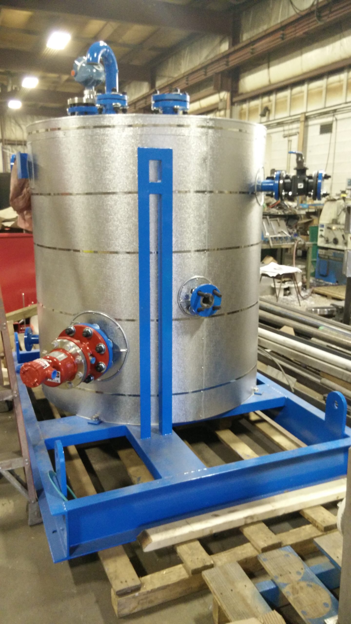
Since some of the fuel oils are high viscosity, the heating is onsite through an inline electric immersion heater. Or if the onsite steam boiler is available, then steam tapped from the utilities steam header is used.
The heavy fuel oils are stored in the storage tanks with floor coil heaters. Heating the oil through steam passing through the floor coils. In the absence of the steam boilers, whether inline or flanged immersion heater type. Electric immersion heaters are also used to reduce the viscosity of fuel oils.
Major components of the Fuel Oil Handling system
A typical fuel oil handling system consists of unloading stations with pumps that unload the heavy fuel oil to the storage tanks. A centrifugal separator separates the sludge from the oil pumping systems. Usually, a centrifugal pump is mounted on a skid to transfer fuel.
Passing through fine filters and strainer to further remove the contaminants. The fuel is transferred from the storage tanks to meet the immediate need of the consumer. Ranging from refineries, power stations, or other industrial facilities. Fuel polishing skid or filtration and heating unit (usually steam from the utility steam header or electric immersion heater inline oil heater type).
In some of the areas which encounter colder weather heat tracing system is required. Efficient for piping and valves, heat insulation system to prevent heat losses of the fuel. Instrumentation system includes radar type fuel oil gauge level, power distribution system, and oil-water separator to remove any condensation.
Sometimes when fuel is getting transferred from the storage tank to the day tank. It may have to go through an oil pressurization station before being sent to the burners for combustion. Day tanks are not mandatory if the storage tanks are close to boilers.
Design considerations for the fuel oil handling system
The bulk storage tank can be below or above ground. Receiving fuel through a fill connection, this tank has level monitoring and leak monitoring. The next important design consideration is the duplex fuel oil transfer skid. Which is the most common arrangement for the systems, that have two pumps side by side. The first pump is sized based on the full function of the system and the second pump is a lag pump or backup.
Fuel polishing skid maintains the quality of fuel and it is more than just filtration skids. Because apart from removing the particulate matter it also removes water through a separator.
For sizing and designing the system, the process starts by determining the amount of oil needed in the entire system. This could be determined by the code, insurance requirements for the mission critical systems, and owner’s or operator’s requirements. Determining the size of day tanks that are local to generators or burners in case of a boiler is the next step.
Post the size determination, an analysis of the pumping frequency helps determine the size of the pumps. Depending on how quickly we need to move the fuel through the system and the consumption rate of the generators at peak load. The input from this step will be used to determine the fuel transfer rate which will determine the size of piping and valves in the system.
Tank Sizing Rules
For sizing the storage tank there are a few factors to consider:
Such as the amount of useable fuel. We need to account for 10% of the ullage which is the area of the tank. That cannot be filled with fuel, the drop tube gap (which is the fuel at the bottom of the tank that cannot be pumped by the transfer pumps because the drop tube is a few feet above the bottom of the tank) needs to be accounted for.
The rule of thumb is around 10% of the tank capacity.
Usually, 5% is for testing and exercising the fuel. So, the tank needs to size at a calculated volume X 125% while NFPA 110.5.5.2 now calls for 133% of the designed run time.
Pump Sizing Rules
For sizing the pumps, we need to consider the worst-case scenario. Assuming that the generators or burners are fully loaded, how fast the fuel needs to move from one point in the system to another and all generators are working.
A single pump should be sized 2-3 times the burn rate. If a single pump is feeding multiple-day tanks, the burn rate of all generators should be considered. Flow limiters can be used to restrict flow into a single tank when multiple day tanks are used. Positive displacement pumps have the advantage of providing constant flow even if there is back pressure.
Fuel Polishing system
With the innovation in Fuel polishing skid. It is becoming more important as time passes by. As larger systems are becoming more common with higher fuel storage capacity and ultra-low Sulphur diesel. It poses long term storage challenges.
The fuel strainer removes the large contaminants while the primary filter will provide the first layer of filtration followed by a centrifuge. Which separates the solids and water and removes 30% of the contaminants. The coalescing system is also required to remove water droplets and coalesce solids on a conical baffle. The final filtration is provided by the 2-micron fuel filter.
Another common part of the fuel polishing skid is the inline electric immersion heater which will heat the fuel oil to supply at utility point with required temperatures. Sometimes flanged electric immersion heaters are also used installed in the day tanks while for smaller systems the immersion heater is part of the polishing skid.
 Fuel Oil System Controls
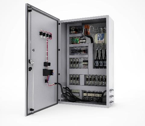
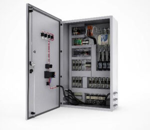
The main control panel is located near the duplex pump skid, and it interacts with the pumps, leak detectors located at day tanks and storage tanks, and level switches on the day tank.
Usually, the four settings on the level switch are used i.e., low, high, to turn the pump on and pump off. Modern control systems or digital control panels are based on programmable logic controls and microprocessors. It can handle a large number of IOs like piping leak detection, multiple level sensors on the main and day tanks, and handle alarms and events.
For mission-critical systems it is becoming quite common for the fuel oil control system to interact with the Building Automation System (BAS) or Building Management System (BMS).
Wattco’s Heaters Helping Oil & Gas Industries
In the rigorous contexts of the oil and gas industry—heavy viscosity fluids, extreme temperatures, and remote sites are all commonplace, and Wattco’s electric heating products deliver dependable performance, and confidence in operations.
Wattco offers immersion, circulation, and flange heaters that are designed specifically for the industry from fuel oil pre-heating to freeze protection in pipelines. For example:
- Heaters in storage tanks keep fluids at optimal temperatures for fluid flow, to prevent thickening or solidifying that disrupts logistics.
- Heaters in pipelines, and in transportation systems, maintain viscosity for easy flowing fluids and can prevent blockages all in cold weather and/or remote sites—these are crucial for safety and uptime.
- In the refining and petrochemical processes, instrumentation with precision and low-watt-density designs create a controlled heat on heavy oils and specialty fluids to minimise the stress on the heating elements, extending their life.
Focused on efficiency, safety, and engineered-to-specification, Wattco heaters work best for upstream, midstream, and downstream operations, enabling companies to meet the evolving demands of industry in a way that wastes less energy and saves on maintenance. From viscosity control, to freeze protection, and processing heat, Wattco heaters offer engineered heating solutions specifically for oil & gas applications.