
Heat Exchanger Configurations
Heat exchangers come in what sometimes seems like an infinite variety of configurations to fit the limitless number of heat transfer situations. Other names include enhanced surfaces, heat sinks, heat dissipators, heat concentrators, and many more. Even restricting our attention to fluid-to-fluid heat exchangers, there is an enormous number of different configurations.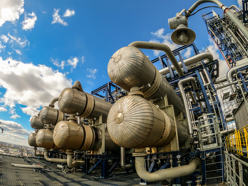
Many fluid-to-fluid heat exchanger calculations can be couched in terms described by the easy-to-visualize cases represented by counterflow and parallel flow concentric pipe heat exchangers.
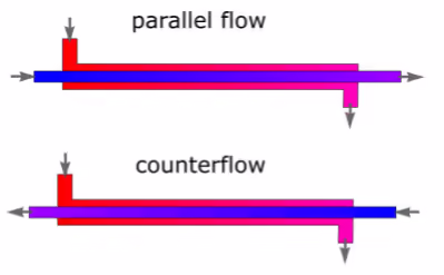
In these two flow configurations, one fluid flows through a central pipe, while the other flows in the annulus between the central pipe and a larger pipe. For rudimentary analysis, it doesn’t matter which flow passage contains which fluid (hot or cold). The temperature distribution along the length of the heat exchangers would look something like this:
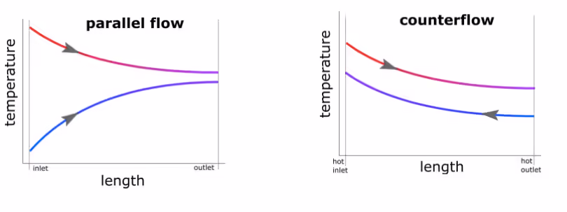
Note that in the parallel flow configuration, the cold outlet can never be warmer than the hot outlet. Just as the hot outlet can never be cooler than the cold outlet. Conversely, both scenarios can occur in the counterflow configuration, as shown in the illustration.
We can think a little bit about the heat transfer for these two configurations in qualitative terms before we get more technical. Recall that the rate of heat transfer is always proportional to a temperature difference. In the parallel flow case, there is a large temperature difference between the two streams near the inlets.
As well as a much smaller temperature difference near the outlets. Potentially falling all the way to zero in the hypothetical case of an infinitely long heat exchanger. Meanwhile, for the counterflow case, the temperature difference will be more uniform across the entire length.
Heat Transfer Rates
We can use the subscripts “o” to designate “outlet” and “i” to designate “inlet” and “c” to signify the cold side, and “h” to signify the hot side. With this nomenclature, and doing an energy balance on each stream separately, we can write:
Q=mh*cph*(Th,o–Th,i)
Q=mc*cpc*(Tc,o–Tc,i)
Where Q is the rate of heat transfer between the two streams, m and cp are the mass flow rate and fluid heat capacity respectively, and T is the temperature. These equations work exactly as written for both parallel flow and counterflow heat exchanger configurations because they are simply energy balances on the two flows. With two independent equations, we can determine a maximum of two unknowns. So if everything else were known, we could calculate the two outlet temperatures. Or, we could determine one outlet temperature and the rate of heat transfer.
Heat Transfer Coefficient
A third equation can be constructed by defining an overall heat transfer coefficient (U) between the two streams as:
U≡ (Q/A)/∆T
Where Q is the rate of heat transfer, A is the heat transfer area, and ΔT is a temperature difference. While Q and A are unambiguous, it is clear from the temperature distributions that the temperature difference between the two streams varies with position. So it isn’t immediately clear which ΔT is appropriate even in the relatively simple cases of concentric tube heat exchangers. By analyzing a differential element of the heat exchanger, and then integrating over the length, it can be shown that the appropriate ΔT is the “log-mean temperature difference” defined in this post:
Now with three equations, three unknowns can be determined. This might include both outlet temperatures and the overall heat transfer coefficient, or both outlet temperatures and the rate of heat transfer. In some cases, the complex expression for the log-mean temperature difference leads to the necessity for an iterative solution.
Phase Change
In some situations, phase change might be present on one side of the heat exchanger. For fluids, this could be boiling on the cold side or condensation on the hot side. In these cases, the temperature profiles would look like this:
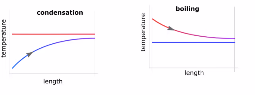 The concepts of counterflow and parallel flow become moot when phase change is present, and the energy balance for the side experiencing phase change becomes:
Q=m*hfg
Where hfg is the heat of vaporization or heat of condensation for the fluid undergoing phase change and m is the mass flow rate at which the fluid is condensing or boiling.
Other heat exchanger configurations such as crossflow heat exchangers, and shell-and-tube heat exchangers with various numbers of shells and various numbers of tube passes in each, are commonly handled with correlations that provide factors to modify the basic equations presented here.
Biography

James Stevens is a professor in the mechanical and aerospace engineering department at the University of Colorado at Colorado Springs. His background is in numerical and analytical heat transfer analysis covering both steady-state and transient situations with applications to thermal history, thermal response, electronic cooling, temperature profiles, thermal design, heat flow rate determination and more. He also works in applied thermodynamics with applications for renewable energy, HVAC, air engines, novel heat engines, and more. He has over 30 years of experience in higher education teaching undergraduate and graduate classes, performing research, doing course and curriculum development, and advising students.